Animatronics
- Tombstone Ghoul
- WLED
- MP3 sound control
- Jolly Roger
- animated eyes
- ESP32 Mesh Network for Halloween Prop Control
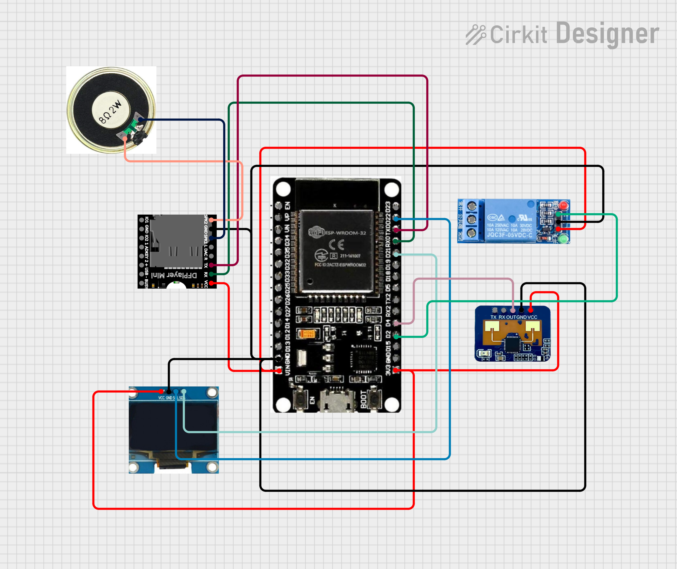
Tombstone Ghoul
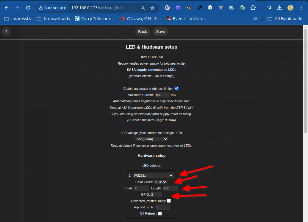
WLED
DO NOT select a beta version - wifi settings will not work.
MP3 sound control
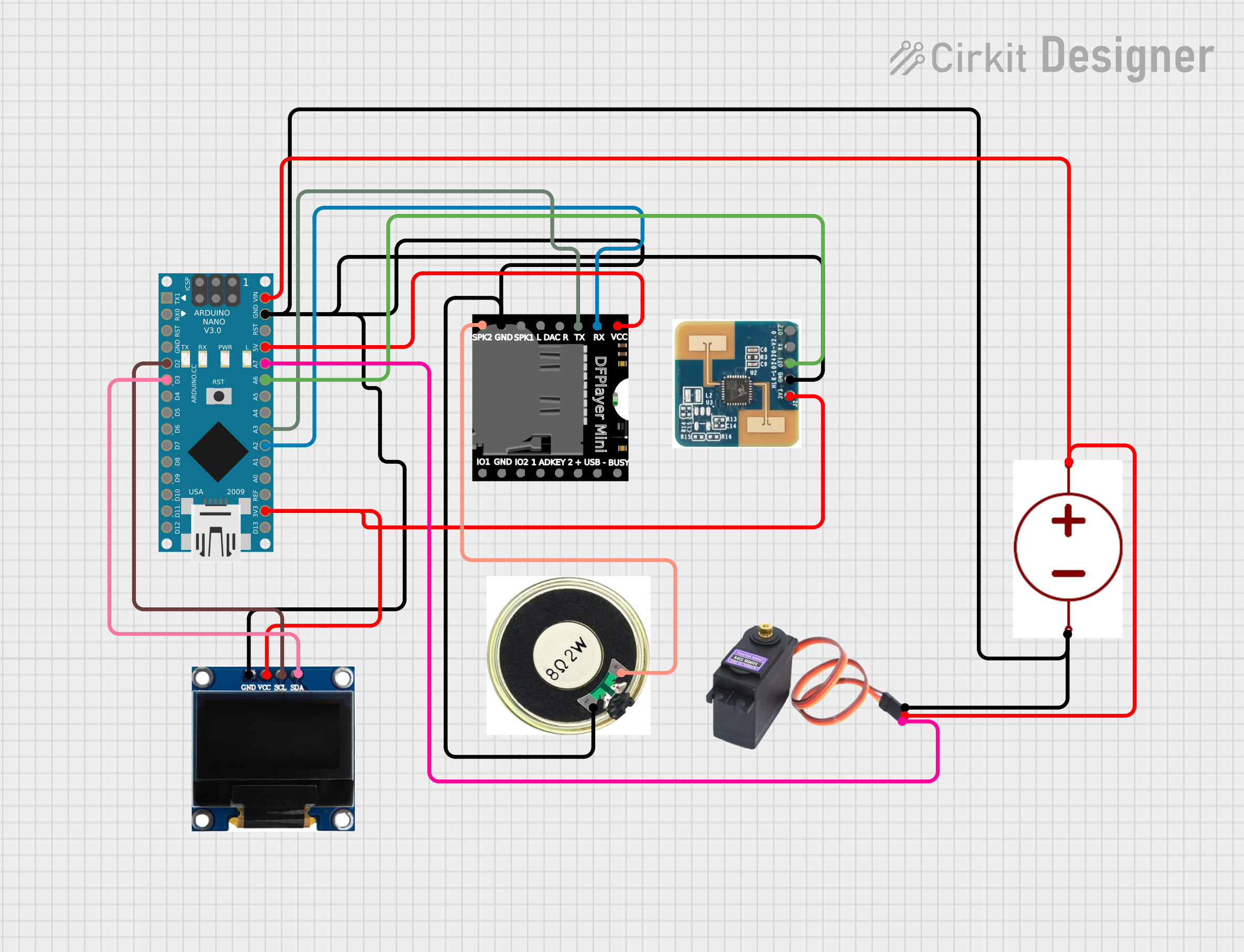
This simple project will use a mp3 player, a simple, recycled speaker, and arduino and a HLK-LD2420 human motion sensor to play sounds when a human walks past the device.
sketch code:
/*
 * Arduino Sketch for Motion-Activated MP3 Playback, Servo Control, and Display
 *
 * This code interfaces with an LD2420 MMWave Sensor to detect motion. Upon
 * detecting motion, it commands a DF Player Mini to play an MP3 file, controls
 * an MG996R servo motor to rotate 45 degrees, and updates an SSD1306 I2C
 * display. The system uses an Arduino Nano as the main controller.
 */

#include <SoftwareSerial.h>
#include <DFRobotDFPlayerMini.h>
#include <Servo.h>
#include <Wire.h>
#include <Adafruit_SSD1306.h>

// Pin definitions
#define SERVO_PIN A7
#define DFPLAYER_RX_PIN A2
#define DFPLAYER_TX_PIN A3
#define SENSOR_PIN A6
#define OLED_RESET -1
#define SCREEN_WIDTH 128
#define SCREEN_HEIGHT 64

// Create objects
SoftwareSerial mySoftwareSerial(DFPLAYER_RX_PIN, DFPLAYER_TX_PIN);
DFRobotDFPlayerMini myDFPlayer;
Servo myServo;
Adafruit_SSD1306 display(SCREEN_WIDTH, SCREEN_HEIGHT, &Wire, OLED_RESET);

void setup() {
  // Initialize serial communication
  mySoftwareSerial.begin(9600);
  Serial.begin(9600);

  // Initialize DFPlayer
  if (!myDFPlayer.begin(mySoftwareSerial)) {
    Serial.println("Unable to begin DFPlayer Mini");
    while (true);
  }
  myDFPlayer.volume(20);  // Set volume level (0-30)

  // Initialize Servo
  myServo.attach(SERVO_PIN);
  myServo.write(0);  // Set initial position

  // Initialize sensor pin
  pinMode(SENSOR_PIN, INPUT);

  // Initialize display
  if (!display.begin(SSD1306_I2C_ADDRESS, 0x3C)) {
    Serial.println("SSD1306 allocation failed");
    for (;;);
  }
  display.display();
  delay(2000);
  display.clearDisplay();
  display.setTextSize(1);
  display.setTextColor(SSD1306_WHITE);
  display.setCursor(0, 0);
  display.println("System Ready");
  display.display();
}

void loop() {
  // Check for motion detection
  if (digitalRead(SENSOR_PIN) == HIGH) {
    // Play MP3 file
    myDFPlayer.play(1);  // Play the first track

    // Rotate servo 45 degrees
    myServo.write(45);
    delay(1000);  // Wait for 1 second

    // Return servo to initial position
    myServo.write(0);
    delay(1000);  // Wait for 1 second

    // Update display
    display.clearDisplay();
    display.setCursor(0, 0);
    display.println("Motion Detected!");
    display.display();
    delay(2000);
    display.clearDisplay();
    display.setCursor(0, 0);
    display.println("System Ready");
    display.display();
  }
}
Basic Wiring
Jolly Roger
Overview
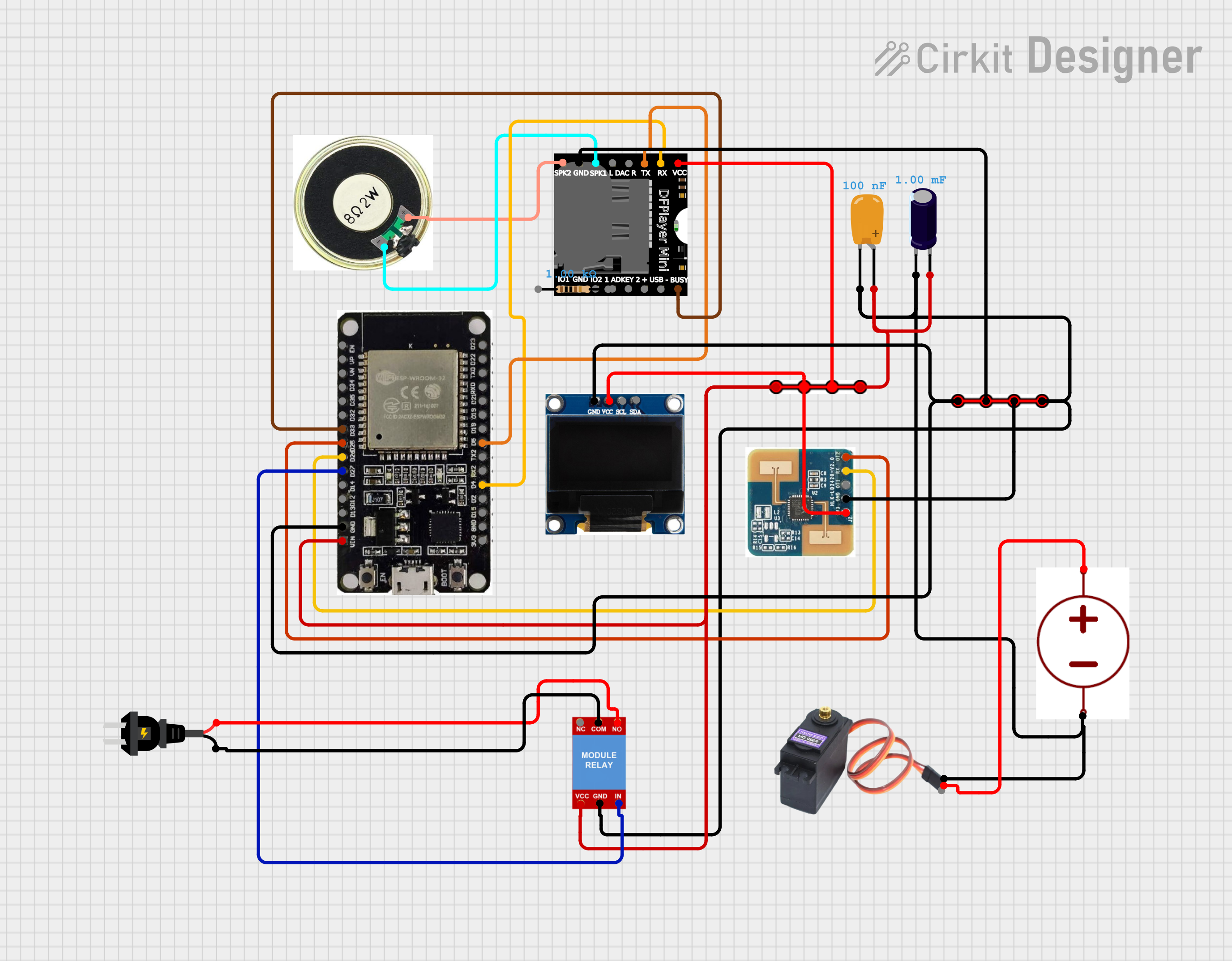
This project implements a distributed network of Halloween animatronics controlled by ESP32 microcontrollers. The system is organized around a master/slave architecture, with the Jolly Roger animatronic acting as the master unit and several additional animatronics operating as synchronized slaves. Communication between units is handled wirelessly over Wi-Fi (esp-now), allowing for coordinated, scalable effects.
animated eyes
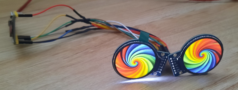
Find a ralatively square image, and if not square, use gimp or an equivalent image editor to crop it to square. Idealy resize it to match your display (240x240 for round displays), then uoload the image to https://impressto.ca/bmp_converter.php Source: https://github.com/impressto/bmp-to-c
If the image was not the correct size, you can resize it in the tool above. Once you save the new c header file, you can save it to your esp32 or arduino source folder and include it in the head.
Source code for the esp32 is here: https://github.com/impressto/esp_lcd_eyes
Demo:
ESP32 Mesh Network for Halloween Prop Control
This project uses a mesh network of ESP32 microcontrollers communicating via ESP-NOW to coordinate a set of Halloween props. The goal is to create synchronized, responsive effects triggered by motion — perfect for haunted house setups or outdoor displays.
System Overview
The network consists of one master controller and multiple slave controllers:
-
Master Node:
Acts as the central coordinator. It’s equipped with a motion sensor (such as a PIR sensor) that detects when someone approaches.
When motion is detected, the master broadcasts a “trigger” message over ESP-NOW to all slave nodes. -
Slave Nodes:
Each slave node controls an individual prop (e.g., fog machine, servo motor, LED lighting, sound module, etc.).
Upon receiving the master’s trigger message, the slave performs its assigned action — for example, moving a prop, flashing lights, or playing a sound.
Once the action is complete, the slave sends a “completed” message back to the master.
Communication Flow
-
Motion Detection:
The master’s PIR sensor detects movement. -
Broadcast Trigger:
The master sends a “motion detected” message via ESP-NOW to all registered slave devices. -
Action Execution:
Each slave performs its programmed effect or animation. -
Completion Feedback:
After finishing, each slave sends a “done” signal to the master. -
Reset or Cooldown:
Once the master receives all “done” signals (or after a timeout), it resets the system and waits for the next motion event.
Key Features
-
ESP-NOW protocol allows for low-latency, Wi-Fi-free communication — no router or internet required.
-
Scalable design — easily add or remove props by pairing additional ESP32s.
-
Bidirectional communication ensures the master knows when all props have completed their sequences.
-
Energy-efficient — nodes can sleep between triggers.
-
Highly customizable — each slave can have its own timing, behavior, or randomized effect.
Example Use Case
-
Master detects motion → broadcasts “TRIGGER”
-
Slave 1 (fog machine): starts fog → sends “DONE” after 10 seconds
-
Slave 2 (LED lights): flashes red and orange → sends “DONE” after 5 seconds
-
Slave 3 (servo skeleton): waves arm → sends “DONE” after 8 seconds
-
Once all “DONE” signals are received, the master resets and waits for the next visitor.
List of mac addresses currently in use:
master (detects motion): FC:B4:67:55:A5:24
sound player: 08:D1:F9:EE:A0:B0