Jolly Roger
Overview
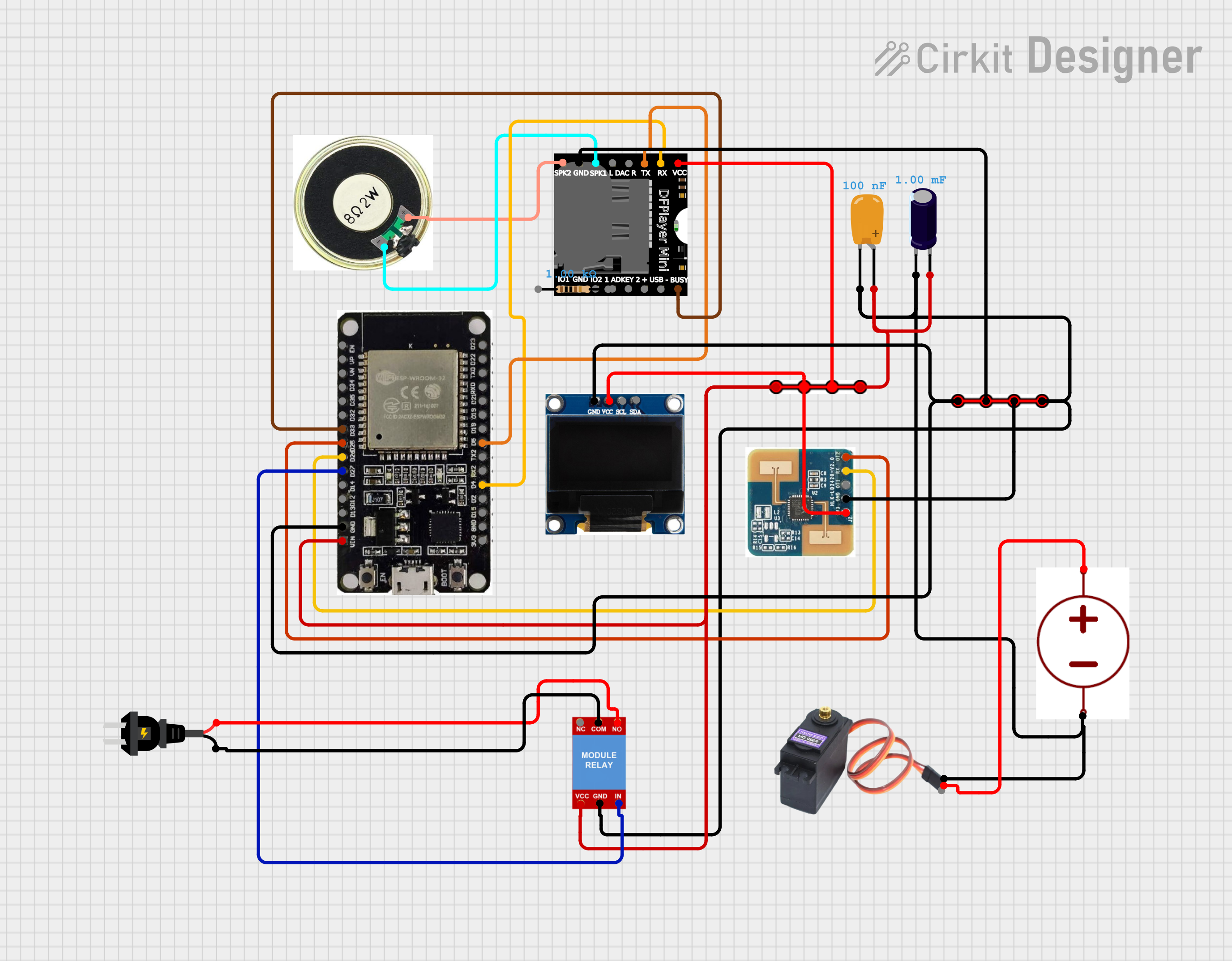
This project implements a distributed network of Halloween animatronics controlled by ESP32 microcontrollers. The system is organized around a master/slave architecture, with the Jolly Roger animatronic acting as the master unit and several additional animatronics operating as synchronized slaves. Communication between units is handled wirelessly over Wi-Fi (esp-now), allowing for coordinated, scalable effects.
Overview
-
Each animatronic is controlled by an ESP32. Master has an LD2410 radar sensor to detect human presence and broadcasts triggers to slaves.
-
Audio: DFPlayer Mini on every unit.
-
Motion: SG90 hobby servos (powered from a 5V supply).
-
Lighting: addressable LEDs (WS2812-style) or simple LED strings — powered from 5V.
-
Eyes: GC9A01 round SPI LCD.
Power & decoupling
-
Supply rails:
-
5V for servos, DFPlayer, LEDs, speakers (if using amp) — recommended common supply for power-hungry parts.
-
3.3V for ESP32 logic (ESP32's regulator when using 5V VIN).
-
-
Common ground: absolutely tie the 5V and ESP32 ground together.
-
Decoupling for servos & LEDs:
-
Add a 1000 μF electrolytic capacitor (or larger depending on the number of servos) close to the servo/LED power feed.
-
Add 0.1 μF ceramic capacitors near ESP32 Vcc pins.
-
-
Wire gauge: use thicker wires (20–18 AWG) for servo + LED power if several are in parallel to avoid voltage drop.
Master (Jolly Roger) wiring (high level)
-
ESP32 VCC -> 3.3V (or VIN from 5V via onboard regulator)
-
LD2410
-
VCC -> 5V (or module-specified supply)
-
GND -> common GND
-
Output -> ESP32 BUSY/INT pin (see section 5)
-
-
DFPlayer Mini
-
VCC -> 5V
-
GND -> GND
-
RX/TX -> ESP32 UART (use hardware UART, see section 6)
-
-
Servos (SG90)
-
VCC -> 5V rail
-
GND -> GND
-
Signal -> ESP32 PWM-capable pin
-
-
LEDs -> 5V + data pin to ESP32 (with 470Ω series on the data line recommended for WS2812)
-
GC9A01 -> SPI bus pins + CS/DC/RST (see section 7)
Slave animatronic wiring (same as master but no LD2410)
-
ESP32, DFPlayer, servos, LEDs, GC9A01 wired exactly like master nodes.
-
Each slave listens for the master broadcast and runs its local routine.
Level shifting & BUSY-pin handling
-
Problem: DFPlayer BUSY may be open-drain/floating or output 5V.
-
If BUSY is 5V TTL: use a resistor divider (example below) or logic level shifter.
Voltage divider (5V -> 3.3V)
BUSY to input-only pins (GPIO34–39)
-
These pins do not support internal pull-ups. If the BUSY line can float (open-drain), add an external 10k pull-up to 3.3V.
-
If you wire BUSY to GPIOs that support
INPUT_PULLUP(e.g., 25, 26, 32, 33), you can usepinMode(pin, INPUT_PULLUP).
DFPlayer wiring notes (UART)
-
DFPlayer VCC -> 5V, GND -> common ground.
-
DFPlayer TX -> ESP32 RX (no level shift needed if DFPlayer TX ≈ 3.3V). If unsure, measure with a multimeter.
-
DFPlayer RX -> ESP32 TX (ESP32 TX is 3.3V, OK for DFPlayer RX).
-
Use one of ESP32 hardware UARTs (UART2 is convenient): e.g. TX2=GPIO17, RX2=GPIO16. These pins are commonly free on dev boards.
-
If these pins conflict in your build, pick other UART-capable pins and configure
Serial2.begin(9600, SERIAL_8N1, rxPin, txPin);.
GC9A01 round LCD (SPI) wiring
Example mapping (shared SPI bus; one CS per display):
-
SCLK -> GPIO18
-
MOSI -> GPIO23
-
MISO -> (not used)
-
CS -> GPIO5 (per display choose unique CS if multiple)
-
DC -> GPIO21
-
RST -> GPIO22
These pins are examples — SPI can be remapped. Keep MOSI/SCLK on the same SPI peripheral for best performance.
Servo wiring & recommendations
-
SG90 signal pins are 3.3V-logic-friendly.
-
Use separate 5V supply for servos to avoid brownouts on ESP32.
-
Add a 1000 μF cap across 5V and GND near servo power feed.
-
Use PWM pins for servo signals; each ESP32 can drive several servos using
ledcorservolibraries.